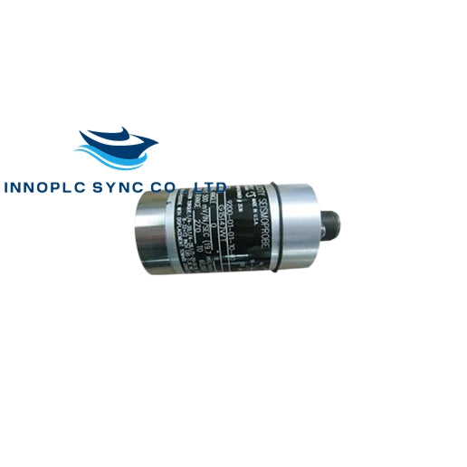
Bently Nevada | 9200-01-05-10-00 | Two-Wire Velocity Seismoprobe Transducer
Bently Nevada Seismoprobe Velocity Transducer Systems are designed to measure absolute vibrations of bearing housings, casings, or structures relative to free space. These two-wire systems consist of a transducer and the corresponding cable.
- Height: 102 mm (4 in) typical (depending on connector option)
- Diameter: 41 mm (1.6 in) typical
-
Weight:
- 9200: 300 grams (10.5 ounces) typical
- 74712: 480 grams (17 ounces) typical
Model Number Format: 9200-AA-BB-CC-DD
-
A: Transducer Mounting Angle/Minimum Operating Frequency Option
- 01: 0 ±2.5, 4.5 Hz (270 cpm)
- 02: 45 ±2.5, 4.5 Hz (270 cpm)
- 03: 90 ±2.5, 4.5 Hz (270 cpm)
- 06: 0 ±100, 10 Hz (600 cpm)
- 09: 0 ±180, 15 Hz (900 cpm)
-
B: Connector/Cable Option
- 01: Top Mount (no cable)
- 02: Side Mount (no cable)
- 05: Terminal block top mount (no cable)
- 10: 10 feet (3.0 meters)
- 15: 15 feet (4.6 meters)
- 22: 22 feet (6.7 meters)
- 32: 32 feet (9.8 meters)
- 50: 50 feet (15.2 meters)
-
C: Mounting Base Option
- 01: Circular; 1/4-20 UNC stud
- 02: Circular; 1/4-28 UNF stud
- 03: Rectangular flange
- 04: Circular; with three 8-32 threaded studs on a 44 mm (1.75 in) diameter bolt circle
- 05: No base; 1/2-20 UNF-3A stud
- 06: Isolated circular 1/4-20 UNC stud
- 07: Isolated circular 1/4-28 UNF stud
- 08: Isolated rectangular flange
- 09: Isolated circular 5/8-18 UNF stud
- 10: Circular; M10X1 stud
- 11: Isolated circular M10X1
- 12: Isolated circular 1/2-20 UNF-2A
-
D: Agency Approval Option
- 00: No Approvals
- 01: CSA
- 04: ATEX/IECEx
-
9200-01-10-01-00:
- Transducer Mounting Angle: 0 ±2.5, 4.5 Hz (270 cpm)
- Connector/Cable: Top Mount, 10 feet (3.0 meters)
- Mounting Base: Circular; 1/4-20 UNC stud
- Agency Approval: No Approvals
Bently Nevada | 9200-01-05-10-00 | Two-Wire Velocity Seismoprobe Transducer


Bently Nevada | 9200-01-05-10-00 | Two-Wire Velocity Seismoprobe Transducer
Bently Nevada Seismoprobe Velocity Transducer Systems are designed to measure absolute vibrations of bearing housings, casings, or structures relative to free space. These two-wire systems consist of a transducer and the corresponding cable.
- Height: 102 mm (4 in) typical (depending on connector option)
- Diameter: 41 mm (1.6 in) typical
-
Weight:
- 9200: 300 grams (10.5 ounces) typical
- 74712: 480 grams (17 ounces) typical
Model Number Format: 9200-AA-BB-CC-DD
-
A: Transducer Mounting Angle/Minimum Operating Frequency Option
- 01: 0 ±2.5, 4.5 Hz (270 cpm)
- 02: 45 ±2.5, 4.5 Hz (270 cpm)
- 03: 90 ±2.5, 4.5 Hz (270 cpm)
- 06: 0 ±100, 10 Hz (600 cpm)
- 09: 0 ±180, 15 Hz (900 cpm)
-
B: Connector/Cable Option
- 01: Top Mount (no cable)
- 02: Side Mount (no cable)
- 05: Terminal block top mount (no cable)
- 10: 10 feet (3.0 meters)
- 15: 15 feet (4.6 meters)
- 22: 22 feet (6.7 meters)
- 32: 32 feet (9.8 meters)
- 50: 50 feet (15.2 meters)
-
C: Mounting Base Option
- 01: Circular; 1/4-20 UNC stud
- 02: Circular; 1/4-28 UNF stud
- 03: Rectangular flange
- 04: Circular; with three 8-32 threaded studs on a 44 mm (1.75 in) diameter bolt circle
- 05: No base; 1/2-20 UNF-3A stud
- 06: Isolated circular 1/4-20 UNC stud
- 07: Isolated circular 1/4-28 UNF stud
- 08: Isolated rectangular flange
- 09: Isolated circular 5/8-18 UNF stud
- 10: Circular; M10X1 stud
- 11: Isolated circular M10X1
- 12: Isolated circular 1/2-20 UNF-2A
-
D: Agency Approval Option
- 00: No Approvals
- 01: CSA
- 04: ATEX/IECEx
-
9200-01-10-01-00:
- Transducer Mounting Angle: 0 ±2.5, 4.5 Hz (270 cpm)
- Connector/Cable: Top Mount, 10 feet (3.0 meters)
- Mounting Base: Circular; 1/4-20 UNC stud
- Agency Approval: No Approvals
