1747-L542 | Allen-Bradley | Unidade de Processamento
Descrição
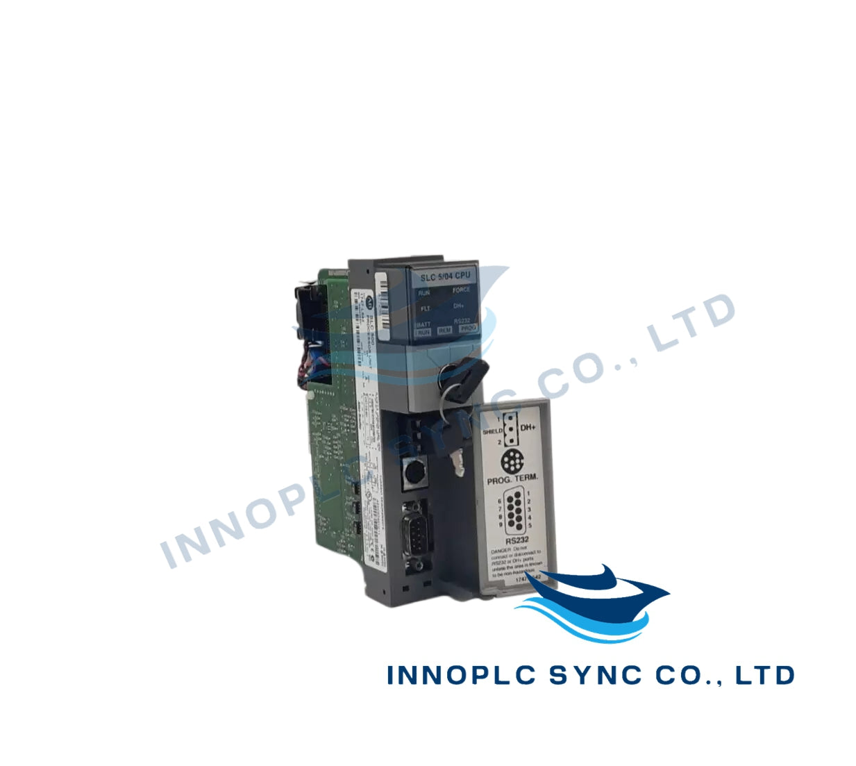
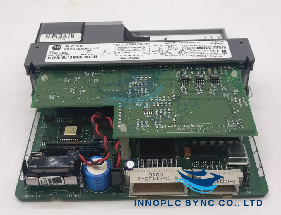
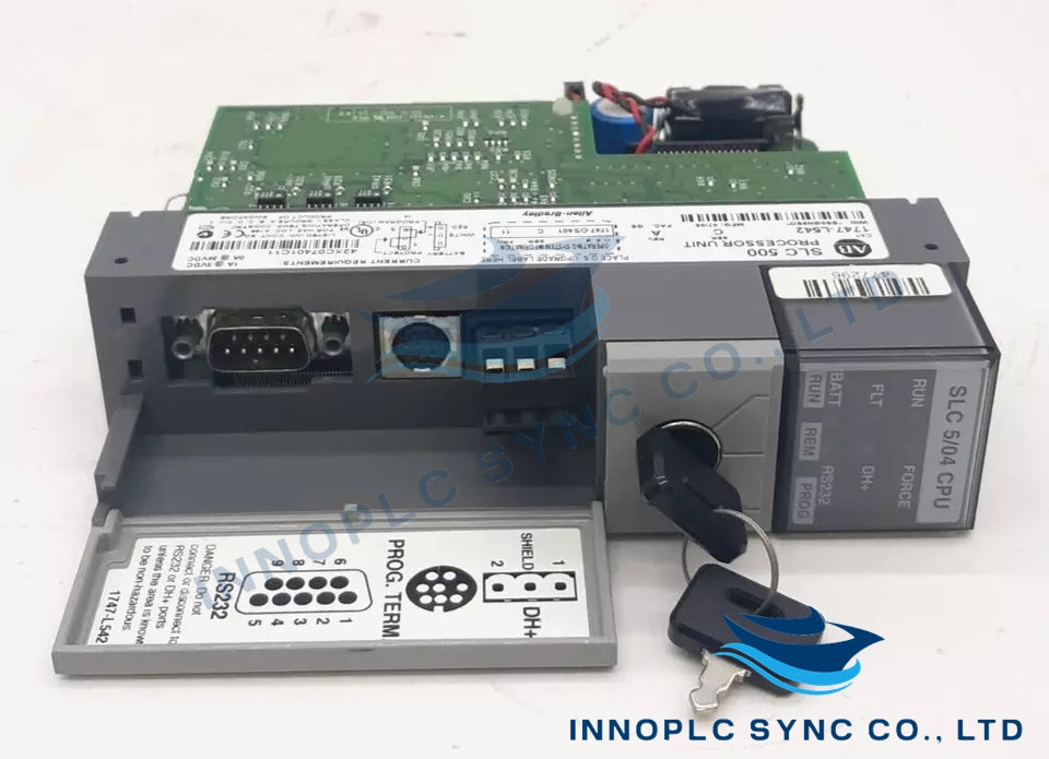
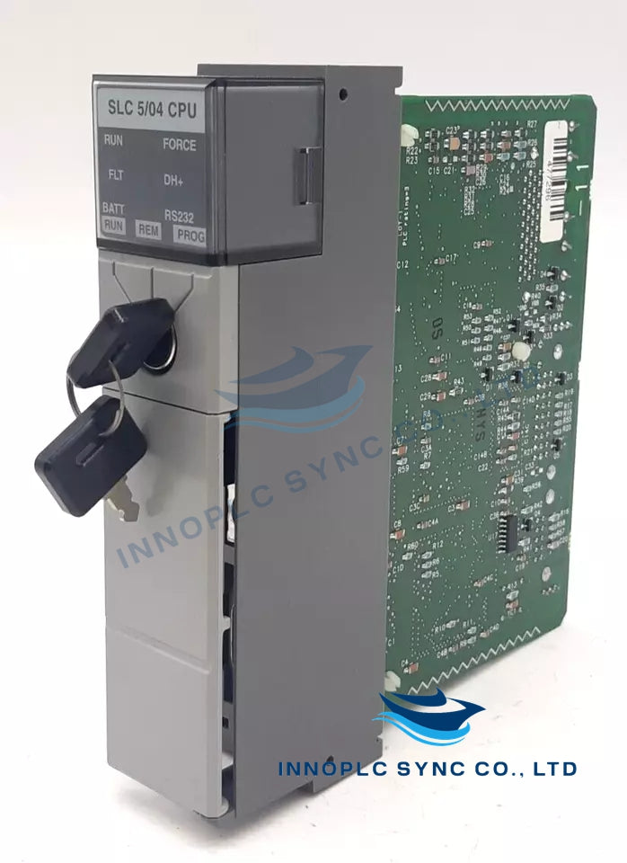
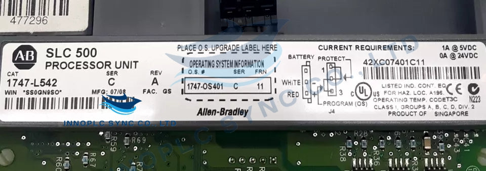
O 1747-L542 é um processador na série de hardware modular SLC 500, projetado para controle lógico programável avançado. Suporta programação poderosa em lógica ladder, até 3840 pontos de I/O e múltiplos canais de comunicação. O processador inclui RAM com bateria de backup, um interruptor de chave para modos de operação e conformidade com os padrões de segurança dos EUA, Canadá e Europa.
Características
- Funções matemáticas avançadas: trigonométricas, PID, exponenciais, de ponto flutuante.
- Endereçamento indireto e endereçamento lógico ASCII.
- Flash PROM para atualizações de firmware.
- Módulo de memória flash EPROM opcional.
- Modos de chave: RUN, REMote, PROGram (limpar falhas).
- RAM com bateria para retenção de dados.
- Listado pela UL, em conformidade com a CE, marcado com C-Tick.
Especificações técnicas
-
Consumo de energia:
- 5 Vcc: 1.000 A
- 24 Vcc: 0,000 A (somente processador)
-
Capacidade total de fornecimento de energia:
- Para chassis com este processador, a fonte de alimentação 1746-P4 é recomendada, fornecendo 10 A a 5V cc e 2,88 A a 24V cc.
-
Dissipação de calor:
- Total de Watts: 4,00 W
-
Compatibilidade do módulo de memória:
- 1747-M1: 1 K Palavras de Usuário EEPROM
- 1747-M2: 4 K palavras do usuário EEPROM
- 1747-M5: Soquete adaptador
-
Bateria de reserva:
- A bateria de lítio fornece backup para a RAM CMOS.
- Um indicador de estado de BATERIA BAIXA em vermelho alerta quando a voltagem da bateria cai abaixo de um nível de limiar.
- A bateria pode ser substituída enquanto o processador está ligado.
-
Canais de Comunicação:
- DH-485, DF1 ou canal ASCII 0
- DH-485 Canal 1
-
Indicadores de status:
- RUN (Cor: verde): Ligado (constante) - O processador está no modo Run.
- FLT (Cor: vermelho): A piscar (ao ligar) - O processador não foi configurado.
- FLT (Cor: vermelho): A piscar (durante a operação) - O processador deteta um erro grave.
- FLT (Cor: vermelho): Ligado (fixo) - Um erro fatal está presente (sem comunicação).
- FLT (Cor: vermelho): Desligado - Não há erros.
- FORÇA, DH+, RS232, BAT, EXECUTAR REM PROG
-
Sistema operacional:
- Suporta a funcionalidade de lista de múltiplos pontos (processador SLC 5/04 OS302 ou posterior).
-
Instruções de instalação:
- Desligue sempre a alimentação antes de remover o processador ou de inserir/remover o módulo de memória.
- Os módulos de memória são montados em suportes ou têm conectores que são codificados para evitar uma instalação inadequada.
- Manuseie os módulos de memória pelas extremidades do suporte ou pelas bordas da carcaça de plástico para evitar danos causados por óleo da pele, sujeira e cargas eletrostáticas.
1747-L542 | Allen-Bradley | Unidade de Processamento
1747-L542 | Allen-Bradley | Unidade de Processamento
Descrição
O 1747-L542 é um processador na série de hardware modular SLC 500, projetado para controle lógico programável avançado. Suporta programação poderosa em lógica ladder, até 3840 pontos de I/O e múltiplos canais de comunicação. O processador inclui RAM com bateria de backup, um interruptor de chave para modos de operação e conformidade com os padrões de segurança dos EUA, Canadá e Europa.
Características
- Funções matemáticas avançadas: trigonométricas, PID, exponenciais, de ponto flutuante.
- Endereçamento indireto e endereçamento lógico ASCII.
- Flash PROM para atualizações de firmware.
- Módulo de memória flash EPROM opcional.
- Modos de chave: RUN, REMote, PROGram (limpar falhas).
- RAM com bateria para retenção de dados.
- Listado pela UL, em conformidade com a CE, marcado com C-Tick.
Especificações técnicas
-
Consumo de energia:
- 5 Vcc: 1.000 A
- 24 Vcc: 0,000 A (somente processador)
-
Capacidade total de fornecimento de energia:
- Para chassis com este processador, a fonte de alimentação 1746-P4 é recomendada, fornecendo 10 A a 5V cc e 2,88 A a 24V cc.
-
Dissipação de calor:
- Total de Watts: 4,00 W
-
Compatibilidade do módulo de memória:
- 1747-M1: 1 K Palavras de Usuário EEPROM
- 1747-M2: 4 K palavras do usuário EEPROM
- 1747-M5: Soquete adaptador
-
Bateria de reserva:
- A bateria de lítio fornece backup para a RAM CMOS.
- Um indicador de estado de BATERIA BAIXA em vermelho alerta quando a voltagem da bateria cai abaixo de um nível de limiar.
- A bateria pode ser substituída enquanto o processador está ligado.
-
Canais de Comunicação:
- DH-485, DF1 ou canal ASCII 0
- DH-485 Canal 1
-
Indicadores de status:
- RUN (Cor: verde): Ligado (constante) - O processador está no modo Run.
- FLT (Cor: vermelho): A piscar (ao ligar) - O processador não foi configurado.
- FLT (Cor: vermelho): A piscar (durante a operação) - O processador deteta um erro grave.
- FLT (Cor: vermelho): Ligado (fixo) - Um erro fatal está presente (sem comunicação).
- FLT (Cor: vermelho): Desligado - Não há erros.
- FORÇA, DH+, RS232, BAT, EXECUTAR REM PROG
-
Sistema operacional:
- Suporta a funcionalidade de lista de múltiplos pontos (processador SLC 5/04 OS302 ou posterior).
-
Instruções de instalação:
- Desligue sempre a alimentação antes de remover o processador ou de inserir/remover o módulo de memória.
- Os módulos de memória são montados em suportes ou têm conectores que são codificados para evitar uma instalação inadequada.
- Manuseie os módulos de memória pelas extremidades do suporte ou pelas bordas da carcaça de plástico para evitar danos causados por óleo da pele, sujeira e cargas eletrostáticas.
